Pico
Pico Boards
Let me pull the official specs to get the Pico 2 family details right.Here’s the current official lineup. There are two generations — Pico 1 (RP2040) and Pico 2 (RP2350) — and each generation comes in four variants that differ by wireless connectivity (the “W” suffix adds Wi-Fi and Bluetooth) and whether headers are presoldered.
All 8 variants
| Board | Chip | Wireless | Headers | SWD connector |
|---|---|---|---|---|
| Pico | RP2040 | No | No | Castellated pads, bottom edge |
| Pico H | RP2040 | No | Yes | JST-style, bottom edge |
| Pico W | RP2040 | Wi-Fi + BT | No | Through-hole pads, central |
| Pico WH | RP2040 | Wi-Fi + BT | Yes | JST-style, central |
| Pico 2 | RP2350 | No | No | Castellated pads, bottom edge |
| Pico 2 with headers | RP2350 | No | Yes | JST-style, bottom edge |
| Pico 2 W | RP2350 | Wi-Fi + BT | No | Through-hole pads, central |
| Pico 2 W with headers | RP2350 | Wi-Fi + BT | Yes | JST-style, central |
Within each generation the variants are hardware-identical apart from wireless and headers, so the real spec differences are between the two chips:
Core specs by generation
| Spec | Pico 1 (RP2040) | Pico 2 (RP2350) |
|---|---|---|
| CPU | Dual-core Arm Cortex-M0+ | Dual-core Arm Cortex-M33 or dual-core Hazard3 RISC-V (switchable) |
| Max clock | 133 MHz | 150 MHz |
| SRAM | 264 kB | 520 kB |
| On-board flash | 2 MB | 4 MB |
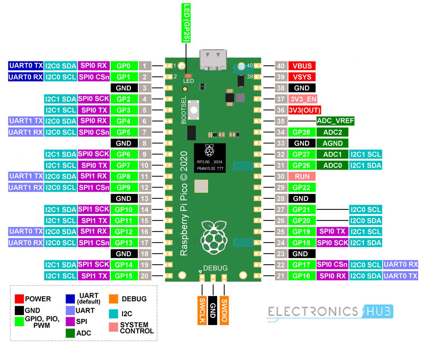
| GPIO | 26 multi-function pins | 26 multi-function pins |
| PIO state machines | 8 | 12 |
| ADC | 3× 12-bit | 3× 12-bit |
| Interfaces | 2× SPI, 2× I2C, 2× UART, 16 PWM | 2× SPI, 2× I2C, 2× UART, 16 PWM |
| USB | USB 1.1 (device + host) | USB 1.1 (device + host) |
Wireless (W variants only): All W boards use the Infineon CYW43439 chip providing single-band 2.4 GHz Wi-Fi 802.11n (with WPA3) and Bluetooth 5.2 (BLE + Classic). The Pico 2 is also hardware and software compatible with Pico 1, and adds a security/crypto feature set on the RP2350.
One thing worth noting if you’re trying to ID a board in hand: the wireless variants moved the debug connector to the centre (under the chip) rather than the bottom edge, and the “2” boards report as RP2350 over USB mass storage rather than RPI-RP2.
Pinout